Ahu Panel Wiring Diagram
If the thermostat has separate e and aux terminals, install a jumper between the two terminals. M24743 zone 2 thermostat m28234b r c e aux y g ob l zone 2 damper thermost at m1 m4 m6 r c eaux y g o l wiring must comply with applicable codes ordinances and regulations.
Ahu Panel Wiring Diagram Wiring Library
Basics 13 valve limit switch legend.
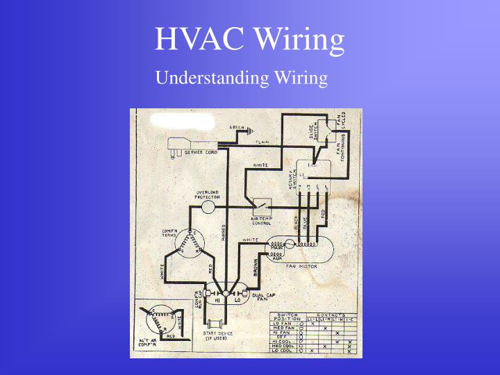
Ahu panel wiring diagram. Hvac control panel wiring diagram. It shows the components of the circuit as simplified shapes and the facility and signal friends in the company of the devices. Ahu controller—air handling unit controller (ahu) 5 note:
Ahu panel wiring diagram wiring diagram is a simplified enjoyable pictorial representation of an electrical circuit. A diagram that represents the elements of a system using abstract, graphic drawings or realistic pictures. Applicable for air handling unit to achieve comfortable.
There are three basic types of wiring diagrams used in the hvac/r industry today, which are: We ensure via intuitive hvac controls that the performance and efficiency of your system is optimised to minimise energy use and. Let's go back and have a look at the control panel, and try and figure out some of the connections by following a wiring diagram.
If test light is lit, go to next step. Johnson controls poteau panel unit facility can lay out, mount, and wire these enclosures to your requirements. An air handling unit (ahu) can only be as good as its weakest link.
The ladder diagram, the line diagram, the installation diagram. 37, abbreviations and symbols refer to other local standards or guidelines usually specified in the contract drawings & documents generic control diagrams using generic symbols to describe and define the Release wire, press the button on top of the terminal.
Always refer to your thermostat or equipment Ahu control panel wiring diagram wiring diagram is a simplified okay pictorial representation of an electrical circuit. Ahu103 low voltage wiring conduit line voltage conduit from 120 vac supply power supply/ transformer relay module fm kit zone.
It shows the components of the circuit as simplified shapes, and the facility and signal friends in the company of the devices. Ga diagram of hvac panel. Not lit, repair open in circuit 141 (brown wire) between instrument panel fuse block and splice s243.
Standard ac with standard air handler and single stage backup heat control wiring standard air handler wire size: Field power wiring ground see rating plate for volts & hertz disconnect per nec see note. Moreover, the heat source for a basic ac system can include heat strips for electric heat or.
Use copper wire (75ºc min) only between disconnect switch and unit. 7.1 overview of central hvac systems. To be wired in accordance with n.e.c.
Air conditioner thermostat wiring details and color code. As i've mentioned in the previous articles, this is a control panel that is used for a system that turns wastewater into clean water. Control diagrams and symbols symbols for hvac system components refer to ashrae fundamentals handbook 2005 chp.
If you are planing to replace the zone controller with smartzone, this diagram is not necessary. The wiring is the most important part o f the panel because the. 3 wires can be run behind the panel, through wire channels on the panel's sides, and must be attached to a wiring anchor with a cable tie.
18 gauge standard single stage heat thermostat standard a/c condenser ac contactor 4 this diagram is to be used as reference for the low voltage control wiring of your heating and ac system. Hu for europe 3 5. Diagram payne heat pump wiring thermostat diagrams ac unit model ph10ja036 furnace fan full i have a pf1mna036 that chart nest for single phase york package units manualzz m seeking guidance on troubleshooting installation instructions manual owner s pdf american standard 3 5 ton by carrier 15 seer r410a hvac manuals.
If any of the original wire, as supplied, must be replaced, use the same or equivalent type wire. Origin is the control transformer and then the r terminal.; Hvac air systems • hvac air systems are made up of:
If test light is not lit, repair open in circuit 141 (black Do not exceed a 60va transformer to power the.

AHU CONTROL PANEL Hvac tech, Paneling, Hvac

Ahu Panel Wiring Diagram

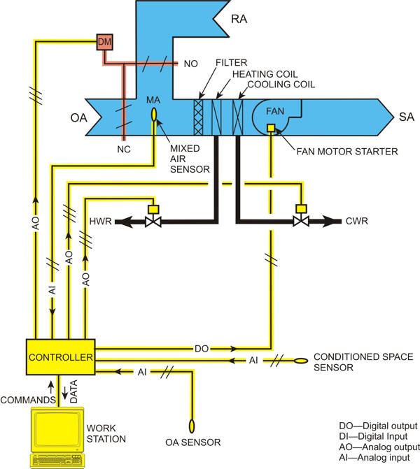
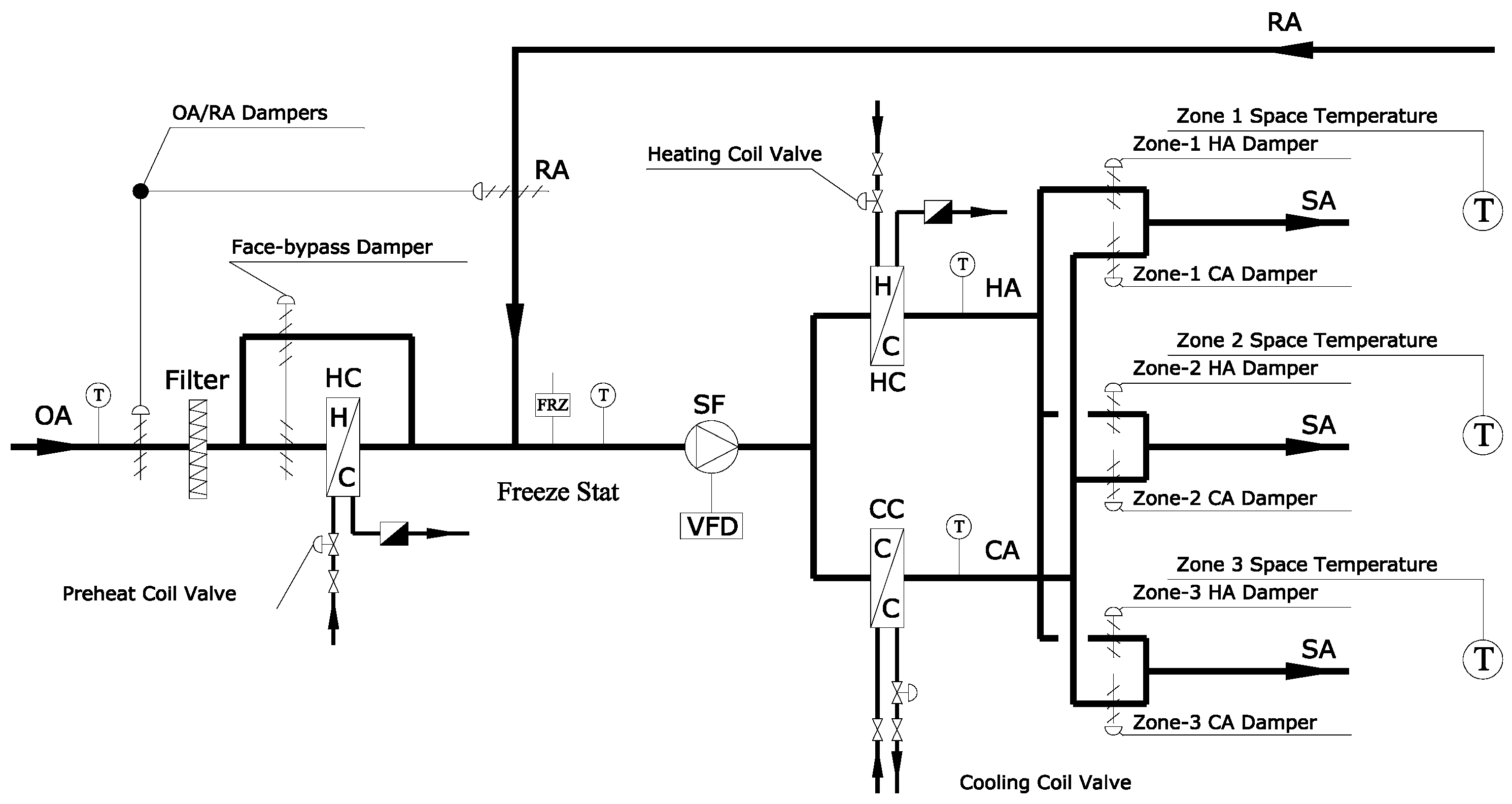
Schematic diagram of conventional AHU control system (single control loop). Download
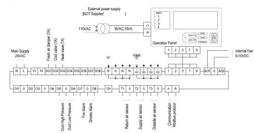
SCI USA AHU Controller Wiring Diagram
Hvac Panel Wiring Diagram Wiring Diagrams Nea

Ahu Starter Panel Wiring Diagram / 2 Library Marian
18 New Hvac Float Switch Wiring Diagram


Ddc Panel Wiring Diagram

Luxaire Air Conditioning Wiring Diagram Source
Variable Frequency Drive Applications in HVAC Systems IntechOpen

I need to know the basic wiring hook up for my hvac to my honeywell hz322 zone system. had a

Ddc Panel Wiring Diagram Pdf

Ahu Starter Panel Wiring Diagram THEINSTRUMENT

HVAC High Voltage Electrical Wiring Hvac, Circuit breaker panel, Refrigeration and air
Repair Guides Heating, Ventilation & Air Conditioning (2002) Hvac Control System

8083 HVAC Service With Wiring Diagram Rennlist Porsche Discussion Forums
Hvac System Two Zone Hvac System


(PDF) A Neural Network Assisted Cascade Control System for Air Handling Unit
Article DDC FOR HVAC SYSTEMS